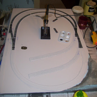
Now I wish I could say that my track work was great, heck I'd even be happy to say it was good, but at best my track work is passable. That's one of the reasons I decided to start with such a small project. I had a bunch of code 80 flex track, cork and blue foam left over from previous projects and that meant that this project was going to be a cheap way to improve my skills in N Scale.
To get started I began test fitting my track at the least forgiving areas my turnouts and crossover. This let me start to get a feel for where I also wanted to break out my power blocks since initially this layout will be all DC based. I used a blue sharpie this time to start noting where I needed to install insulators and what looked like good spots for my feeder wires. Once I was happy with a particular pieces location I used my dremel tool and a pair of tin snips to cut my flex track and then soldered it all together. I really have to admit that I might choose to not solder any special track next time like the cross over and turnouts as later when I had to clean up some poor track work I nearly ruined a turnout. Note that the solder removing ribbon from Radio Shack works wonders to help get a piece of track free.
Here you can see the first half of the inner and outer loops completed. Looks good doesn't it? Well it wasn't I had to remove almost the entire inner loop seen here because I somehow managed to point the soldered joint on that section. Nothing would run properly over that spot. Next time I will really have to pay more attention to this part and not rush it so much. I think i was over confident in my own soldering abilities. I've been soldering for years and years, but soldering track is a lot different than electronics.
This is what the track looked after it was all layed. Again on this half I did have to replace a second section of the inside loop due to a poor connection between two pieces of flex track. You can also see the blue markings noting where the insulators are installed at.
This is a close up of the connection to the rest of the branch that isn't modeled. At some point if this small module works out well I'd like to make it a semi-permanent piece of a larger layout that shows the rest of the branch and possible an interchange with the Pennsy main line and maybe an interchange with another line (NYC, Bessemer or B&O probably). At this point I really haven't given much thought to what comes next. Also in this shot you can see the ground throws that I installed. I have never used these before but I decided to use them this time because I wasn't using switch motors and didn't want to be using those huge atlas switch machines. For a few dollars apiece they are well worth the investment to me. They have an internal spring that makes sure there is some tension on the points in both directions and they lock slightly at each end to help maintain the points connection to the rails. Plus they were super easy to install.
As I mentioned above I tried to repair some of the bad connections before I replaced them. Here is my example of what not to do. I used a few larger nails to try and push the inside rail into a better position then I attempted to redo the solder, but that just didn't work. I wound up cutting this whole piece out and putting fresh flex track in. You can also see the newly installed feeder wires and spst power switch that I installed to turn this section of rail on and off from the power bus.
Monday, December 15, 2008
West Forge: Laying the Track
Labels:
Model Railroad,
N Scale,
Pennsy,
Trains,
West Forge
Subscribe to:
Post Comments (Atom)

No comments:
Post a Comment